Table of Contents (Start)
- Topics
- Introducing SevOne
- Login
- Startup Wizard
- Dashboard
- Global Search - Advanced Search
- Report Manager
- Report Attachment Wizard
- Report Properties
- Report Interactions
- Instant Graphs
- TopN Reports
- Alerts
- Alert Archives
- Alert Summary
- Instant Status
- Status Map Manager
- Edit Maps
- View Maps
- FlowFalcon Reports
- NBAR Reports
- Logged Traps
- Unknown Traps
- Trap Event Editor
- Trap Destinations
- Trap Destination Associations
- Policy Browser
- Create and Edit Policies
- Webhook Definition Manager
- Threshold Browser
- Create and Edit Thresholds
- Probe Manager
- Discovery Manager
- Device Manager
- New Device
- Edit Device
- Object Manager
- High Frequency Poller
- Device Summary
- Device Mover
- Device Groups
- Object Groups
- Object Summary
- Object Rules
- VMware Browser
- AWS Plugin
- Azure Plugin (Public Preview)
- Calculation Plugin
- Database Manager
- Deferred Data Plugin
- DNS Plugin
- HTTP Plugin
- ICMP Plugin
- IP SLA Plugin
- JMX Plugin
- NAM
- NBAR Plugin
- Portshaker Plugin
- Process Plugin
- Proxy Ping Plugin
- SDWAN Plugin
- SNMP Plugin
- VMware Plugin
- Web Status Plugin
- WMI Plugin
- xStats Plugin
- Indicator Type Maps
- Device Types
- Object Types
- Object Subtype Manager
- Calculation Editor
- xStats Source Manager
- User Role Manager
- User Manager
- Session Manager
- Authentication Settings
- Preferences
- Cluster Manager
- Maintenance Windows
- Processes and Logs
- Metadata Schema
- Baseline Manager
- FlowFalcon View Editor
- Map Flow Objects
- FlowFalcon Views
- Flow Rules
- Flow Interface Manager
- MPLS Flow Mapping
- Network Segment Manager
- Flow Protocols and Services
- xStats Log Viewer
- SNMP Walk
- SNMP OID Browser
- MIB Manager
- Work Hours
- Administrative Messages
- Enable Flow Technologies
- Enable JMX
- Enable NBAR
- Enable SNMP
- Enable Web Status
- Enable WMI
- IP SLA
- SNMP
- SevOne Data Publisher
- Quality of Service
- Perl Regular Expressions
- Trap Revisions
- Integrate SevOne NMS With Other Applications
- Email Tips and Tricks
- SevOne NMS PHP Statistics
- SevOne NMS Usage Statistics
- Glossary and Concepts
- Map Flow Devices
- Trap v3 Receiver
- Guides
- Quick Start Guides
- AWS Quick Start Guide
- Azure Quick Start Guide (Public Preview)
- Data Miner Quick Start Guide
- Flow Quick Start Guide
- Group Aggregated Indicators Quick Start Guide
- IP SLA Quick Start Guide
- JMX Quick Start Guide
- Metadata Quick Start Guide
- RESTful API Quick Start Guide
- Self-monitoring Quick Start Guide
- SevOne NMS Admin Notifications Quick Start Guide
- SNMP Quick Start Guide
- Synthetic Indicator Types Quick Start Guide
- Topology Quick Start Guide
- VMware Quick Start Guide
- Web Status Quick Start Guide
- WMI Quick Start Guide
- xStats Quick Start Guide
- xStats Adapter - Accedian Vision EMS (TM) Quick Start Guide
- Deployment Guides
- Automated Build / Rebuild (Customer) Instructions
- Generate a Self-Signed Certificate or a Certificate Signing Request
- SevOne Best Practices Guide - Cluster, Peer, and HSA
- SevOne Data Platform Security Guide
- SevOne NMS Implementation Guide
- SevOne NMS Installation Guide - Virtual Appliance
- SevOne NMS Advanced Network Configuration Guide
- SevOne NMS Installation Guide
- SevOne NMS Port Number Requirements Guide
- SevOne NMS Upgrade Process Guide
- SevOne Physical Appliance Pre-Build BIOS and RAID Configuration Guide
- SevOne SAML Single Sign-On Setup Guide
- Cloud Platforms
- Other Guides
- Quick Start Guides
Probe Manager
The Probe Manager enables you to manage IP SLA data from the devices for which you enable the IP SLA plugin. SevOne NMS supports the following Cisco IP SLA probes; DHCP, DLSw, DNS, Echo, Ethernet Jitter, Ethernet Ping, FTP, HTTP, ICMP Jitter, RTP, TCP Connect, UDP Echo, UDP Jitter, Video, VoIP. For details, please refer to chapter IP SLA.
To access the Probe Manager from the navigation bar, click the Applications menu and select Probe Manager.
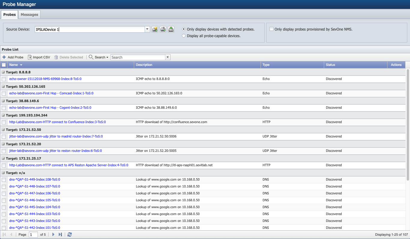
Probe List
While IP SLAs apply to two routers, each IP SLA resides on only one router. SevOne NMS can either run the IP SLA test or can provision the test to the router. The source device is the router on which the IP SLA resides.
-
Click the Source Device drop-down and select a device on which you enable the IP SLA plugin.
-
Click
 to display a link to the Device Summary and links to report templates that are applicable for the device.
 -
Click
 to navigate to the Edit Device page for the source device.
 -
Click
 to provision the IP SLA test on the router.
-
-
Select one of the following options.
-
Select Only Display Devices With Detected Probes to display only devices on which SevOne NMS discovers at least one probe.
-
Select Display All Probe-capable Devices to display all devices on which you enable the IP SLA plugin.
-
-
Select the Only Display Probes Provisioned by SevOne NMS check box to display only the probes SevOne NMS provisions. Leave clear to display all probes for the source device.
The Probes list displays the following information for the probes that meet your filter criteria. Each probe has a target device whose name or IP address displays in the Target separator bars in the list.
-
Name - Displays the name of the probe. Click on the name to display a link to the Object Summary and links to report templates that are applicable for the object. The probes SevOne NMS discovers have the following name convention; type, owner, and probe tag.
-
Description - Displays the description of the probe. The probes SevOne NMS discovers have descriptions based on the probe itself.
-
Type - Displays the type of the probe. Displays as the enumeration form from the CISCO-RTT-MON MIB.
-
Status - Displays Discovered when SevOne NMS runs the test and finds the result on devices for which you enable the IP SLA plugin. Displays Provisioned with SevOne NMS when the device runs the test and sends the result back to SevOne NMS. Displays To Be Deleted if you select to delete the probe.
-
Click
 to view the IP SLA configuration.
Add Probes
Perform the following steps to add a new probe. The Import CSV button enables you to import multiple probes from a .csv file. See the Import CSV section below.
-
Click Add Probe to display the Add Probe pop-up.
-
On the pop-up in the Name field, enter the probe name. This must be unique for the device you select.
-
In the Description field, enter the probe description for user information only.
-
Click the IP SLA Type drop-down and select an IP SLA type. The type you select determines the configuration steps. IP SLA types that are not applicable for the device you select appear in light text and you cannot select those types.
-
If you select DHCP, perform the following configuration steps.
-
Select one of the following options.
-
Select Specify Target By Name to select the name of the target device from a drop-down list in the next step.
-
Select Specify Target By IP Address to enter the IP address of the target device in a text field in the next step.
-
-
In the Target field, either click the drop-down and select the target device by name or enter the target device IP address in the text field (dependent on the selection you make in the previous step).
-
In the Frequency field, enter the number of seconds for how often the router should perform the test. This must be greater than 0 and should be slightly less than the poll frequency of the device.
-
In the Circuit ID field, enter the Cisco Circuiter ID on its CLI. This is a hexadecimal value.
-
In the Remote ID field, enter the remote ID. This is a hexadecimal value.
-
In the Subnet Mask field, enter the Cisco extension to DHCP Option 82 that allows the specification of a subnet. This is a hexadecimal value.
-
Click the Source IP drop-down and select the IP address of the source device.
-
-
If you select DLSw or Echo, perform the following configuration steps.
-
Select one of the following options.
-
Select Specify Target By Name to select the name of the target device from a drop-down list in the next step.
-
Select Specify Target By IP Address to enter the IP address of the target device in a text field in the next step.
-
-
In the Target field, either click the drop-down and select the target device by name or enter the target device IP address in the text field (dependent on the selection you make in the previous step).
-
In the Frequency field, enter the number of seconds for how often the router should perform the test. This must be greater than 0 and should be slightly less than the poll frequency of the device.
-
(Echo only) In the ToS field, enter the type of service (ToS) byte number in the IP header of an IP SLAs operation (number between 0 and 255).
-
(Echo only) Click the Source IP drop-down and select the IP address of the source device.
-
-
If you select DNS, perform the following configuration steps.
-
In the Domain field, enter the complete valid URL of the DNS domain.
-
In the Nameserver field, enter the IP address of the name server.
-
In the Frequency field, enter the number of seconds for how often the router should perform the test. This must be greater than 0 and should be slightly less than the poll frequency of the device.
-
Click the Source IP drop-down and select the IP address of the source device.
-
-
If you select Ethernet Jitter or Ethernet Ping, perform the following configuration steps.
-
In the MPID field, enter the destination Maintenance Point Identifier to test.
-
In the Domain Name field, enter the domain in which the destination maintenance point lies.
-
In the Target VLAN field, enter identifier of the VLAN in which the destination maintenance point lies.
-
In the Target EVC field, enter the Ethernet Virtual Connection in which the maintenance point lies.
-
In the Frequency field, enter the number of seconds for how often the router should perform the test. This must be greater than 0 and should be slightly less than the poll frequency of the device.
-
(Ethernet Jitter only) In the Packet # field, enter the number of packets to send.
-
(Ethernet Jitter only) In the Interval field, enter the number of milliseconds to be the interval between packets.
-
In the CoS field, enter the Ethernet Class of Service.
-
-
If you select FTP, perform the following configuration steps.
-
In the URL field, enter the complete, valid URL of the file to fetch. This must include the ftp:// part and if a user name and password are required, use the following format; username:password@webaddress.
Exampleftp://jerry:password@www.test.com/membersarea
-
In the Frequency field, enter the number of seconds for how often the router should perform the test. This must be greater than 0 and should be slightly less than the poll frequency of the device.
-
In the ToS field, enter the type of service (ToS) for the FTP packets that are sent (number between 0 and 255).
-
Select a Mode option: either Active or Passive.
Passive mode is required if the firewall is enabled on your appliance.
-
Click the Source IP drop-down and select the IP address from which to issue the request. If a router has multiple interfaces and some interfaces do not have access to the FTP server, you must select the IP address of the interface that is to issue the request. If you leave this blank the router attempts to choose the best/closest interface which may not be the interface you want.
-
-
If you select HTTP, perform the following configuration steps.
-
In the URL field, enter the complete, valid URL of the HTTP server.
-
In the Nameserver field, enter the IP address of the name server.
-
In the Frequency field, enter the number of seconds for how often the router should perform the test. This must be greater than 0 and should be slightly less than the poll frequency of the device.
-
In the ToS field, enter the type of service (ToS) byte number in the IP header of an IP SLA operation (number between 0 and 255).
-
Click the Operation drop-down and select an operation.
-
Click the HTTP Version drop-down and select the HTTP version.
-
In the Proxy field, enter the IP address of the proxy.
-
Select the Cache check box to cache the IP SLA.
-
Click the Source IP drop-down and select the IP address of the source device.
-
-
If you select ICMP Jitter, perform the following configuration steps.
-
Select one of the following options.
-
Select Specify Target By Name to select the name of the target device from a drop-down list in the next step.
-
Select Specify Target Device By IP Address to enter the IP address of the target device in a text field in the next step.
-
-
In the Target field, either click the drop-down and select the target device by name or enter the target device IP address in the text field (dependent on the selection you make in the previous step).
-
In the Frequency field, enter the number of seconds for how often the router should perform the test. This must be greater than 0 and should be slightly less than the poll frequency of the device.
-
In the ToS field, enter the type of service (ToS) byte number in the IP header of an IP SLAs operation (number between 0 and 255).
-
In the Packet # field, enter the number of packets to send.
-
In the Interval field, enter the number of milliseconds to be the interval between packets.
-
Click the Source IP drop-down and select the IP address of the source device.
-
-
If you select RTP, perform the following configuration steps.
-
Select one of the following options.
-
Select Specify Target By Name to select the name of the target device from a drop-down list in the next step.
-
Select Specify Target By IP to enter the IP address of the target device in a text field in the next step.
-
-
In the Target field, either click the drop-down and select the target device by name or enter the target device IP address in the text field (dependent on the selection you make in the previous step).
-
Click the Codec drop-down and select the codec to use for the Mean Opinion Score (MOS), and the Impairment/calculated planning impairment factor (ICPIF) score.
-
In the Source Voice Port field, enter the voice port name, such as 0/1/1. This is not a TCP/UDP port number.
-
In the ICPIF Factor field, enter the calculated planning impairment factor number that determines the type of access and how the service is to be used. (0=Conventional Wire Line, 5=Mobility Within Building, 10=Mobility Within Geographic Area, 20=Access to Hard-to Reach Location).
-
In the Frequency field, enter the number of seconds for how often the router should perform the test. This must be greater than 0 and should be slightly less than the poll frequency of the device.
-
In the Duration field, enter the IP SLA duration.
-
Click the Source IP drop-down and select the IP address of the source device.
-
-
If you select TCP Connect or UDP Echo, perform the following configuration steps.
-
Select one of the following options.
-
Select Specify Target By Name to select the name of the target device from a drop-down list in the next step.
-
Select Specify Target By IP Address to enter the IP address of the target device in a text field in the next step.
-
-
In the Target field, either click the drop-down and select the target device by name or enter the target device IP address in the text field (dependent on the selection you make in the previous step).
-
In the Target Port field, enter the port number on which to connect (number between 0 and 65535).
-
In the Frequency field, enter the number of seconds for how often the router should perform the test. This must be greater than 0 and should be slightly less than the poll frequency of the device.
-
In the ToS field, enter the type of service (ToS) byte number in the IP header of an IP SLAs operation (number between 0 and 255).
-
Click the Source IP drop-down and select the IP address of the source device.
-
-
If you select UDP Jitter, perform the following configuration steps.
-
Select one of the following options.
-
Select Specify Target By Name to select the name of the target device from a drop-down list in the next step.
-
Select Specify Target By IP Address to enter the IP address of the target device in a text field in the next step.
-
-
In the Target field, either click the drop-down and select the target device by name or enter the target device IP address in the text field (dependent on the selection you make in the previous step).
-
In the Target Port field, enter the port number on which to connect (number between 0 and 65535).
-
Click the Codec drop-down and select the codec to use for the Mean Opinion Score (MOS) and the Impairment/calculated planning impairment factor (ICPIF) score.
-
In the Frequency field, enter the number of seconds for how often the router should perform the test. This must be greater than 0 and should be slightly less than the poll frequency of the device.
-
In the ToS field, enter the type of service (ToS) byte number in the IP header of an IP SLAs operation (number between 0 and 255).
-
In the Packet # field, enter the number of packets to send.
-
In the Interval field, enter the number of milliseconds to be the interval between packets.
-
Click the Precision drop-down and select the precision that is dependent on the compliance revision (Revision 9 or after) of the sender and target IP SLA, you may be able to poll in microseconds.
-
Click the Source IP drop-down and select the IP address of the source device.
-
-
If you select Video, perform the following configuration steps.
-
Select one of the following options.
-
Select Specify Target By Name to select the name of the target device from a drop-down list in the next step.
-
Select Specify Target By IP Address to enter the IP address of the target device in a text field in the next step.
-
-
In the Target field, either click the drop-down and select the target device by name or enter the target device IP address in the text field (dependent on the selection you make in the previous step).
-
In the Target Port field, enter the port number on which to connect (number between 0 and 65535).
-
In the Source field, enter the IP address of the source device.
-
In the Source Port field, enter the port number of the source device.
-
Click the Video Traffic Profile drop-down.
-
Select IPTV to indicate the profile is for Internet Protocol television (IPTV) which is a system through which television services are delivered using the Internet Protocol Suite over a packet-switched network such as the Internet, instead of being delivered through traditional terrestrial, satellite signal, and cable television formats.
-
Select IPVSC to indicate the profile is for an IP surveillance camera.
-
Select TELEPRESENCE to indicate the profile is for the set of technologies which enable a person to feel as if they were present, or to give the appearance of being present, via telerobotics, at a place other than their true location.
-
-
In the Frequency field, enter the number of seconds for how often the router should perform the test. This must be greater than 0 and should be slightly less than the poll frequency of the device.
-
In the Duration field, enter the IP SLA duration.
-
In the ToS field, enter the type of service (ToS) byte number in the IP header of an IP SLAs operation (number between 0 and 255).
-
-
If you select VoIP, perform the following configuration steps.
-
Click the Detect Point drop-down and select the detect point.
-
In the Called Number field, enter the telephone number called.
-
In the Frequency field, enter the number of seconds for how often the router should perform the test. This must be greater than 0 and should be slightly less than the poll frequency of the device.
-
In the ToS field, enter the type of service (ToS) byte number in the IP header of an IP SLAs operation (number between 0 and 255).
-
In the Source IP field, enter the IP address of the source device.
-
-
-
Click Save.
-
Click
 to delete a probe. This icon does not appear for probes that SevOne NMS discovers because you cannot delete those probes. When you delete a probe, the probe is removed from SevOne NMS and removed from the router. The change takes effect the next time the device is discovered. Until then, the probe displays To Be Deleted.
Import CSV
The Probe CSV Importer enables you to import probes into SevOne NMS. Use any application to create a comma delimited file. The .csv file(s) must be encoded in UTF-8. Complete all required fields. The IP SLA type entry determines what fields are required. Leave the fields that relate to other IP SLA types blank and delimited by the applicable number of commas.
File format for the required fields:
Probe Type, Device Name, IP SLA Type, Name, Description, Frequency, Target, Target Port, ToS, Packet #, Packet Interval, Codec Type, Probe Precision, HTTP Version, URL, Nameserver, Proxy, Cache, Detect Point, Called Number
Conditionally required fields for specific probe types:
MPID, Domain Name, Target VLAN, CoS, Target EVC, Video Traffic Profile, Source Voice Port, ICPIF Factor, Duration, Source IP, Source Port, Mode, Circuit ID, Remote ID, Subnet Mask
The .csv file must contain the following fields:
-
Probe Type – (Required) Enter IP SLA
-
Device Name - (Required) Enter the name of a device that SevOne NMS discovers, including domain name and extension.
-
IP SLA Type - (Required) Enter one of the following: dhcp, dlsw, dns, echo, ethernetJitter, ethernetPing, FTP, http, icmpjitter, RTP, tcpConnect, udpEcho, udpJitter, video, voip
-
Name - (Required) Enter the name for the probe.
-
Description - (Required) Enter the description for the probe.
-
Frequency - (Required) Enter is how frequently the router should perform the test, a number greater than 0.
-
Target - (Required for DHCP, DLSw, Echo, ICMP Jitter, RTP, TCP Connect, UDP Echo, UDP Jitter, Video) - Enter either the valid name of a device in SevOne NMS or a valid IPv4 address.
-
Target Port - (Required for TCP Connect, UDP Echo, UDP Jitter, Video) Enter a number between 0 and 65535.
-
ToS - (Required for DLSw, Echo, FTP, HTTP, ICMP Jitter, TCP Connect, UDP Echo, UDP Jitter, Video, VoIP) Enter a number between 0 and 255. This stands for Type of Service.
-
Packet # - (Required for Ethernet Jitter, ICMP Jitter, UDP Jitter) Enter a number.
-
Interval - (Required for Ethernet Jitter, ICMP Jitter, UDP Jitter) Enter a number.
-
Codec Type - (Required for RTP, UDP Jitter) Enter one of the following: notApplicable, g711ulaw, g711alaw, g729a
-
Precision - (Required for UDP Jitter) Enter one of the following: milliseconds, microseconds
-
HTTP Version - (Required for HTTP) Enter one of the following: 0.9, 1.0, 1.1
-
URL - (Required for FTP, HTTP) Enter a valid URL.
-
Nameserver - (Required for DNS, HTTP) Enter a valid IPv4 address.
-
Proxy - (Required for HTTP) Enter a valid IPv4 address.
-
Cache - (Required for HTTP) Enter either Yes for enabled or No for disabled.
-
Detect Point - (Required for VoIP) Enter one of the following: voipDTAlertRinging, voipDTConnectOK
-
Called Number - (Required for VoIP) Enter a valid phone number.
The .csv file may require some or all of the following fields:
Enter commas to account for all fields up to the last field required for each specific IP SLA type. Leave non-applicable fields empty when not required for the protocol.
Example: Video must have five comma delimited empty fields (for MPID, Domain Name, Target VLAN, CoS, Target EVC) before the four required Video fields. You do not need to enter commas for any subsequent fields.
-
MPID - (Required for Ethernet Jitter, Ethernet Ping) Enter a number.
-
Domain Name - (Required for DNS, Ethernet Jitter, Ethernet Ping) Enter a valid domain.
-
Target VLAN - (Required for Ethernet Jitter, Ethernet Ping) Enter a number between 1 and 4095 (inclusive).
-
CoS - (Required for Ethernet Jitter, Ethernet Ping) Enter a number between 0 and 255.
-
Target EVC - (Required for Ethernet Jitter, Ethernet Ping) Enter a valid number.
-
Video Traffic Profile - (Required for Video) Enter one of the following: IPTV, IPVSC, TELEPRESENCE.
-
Duration - (Required for RTP, Video) Enter a number.
-
Source IP - (Required for DNS, Echo, FTP, HTTP, ICMP Jitter, RTP, TCP Connect, UDP Echo, UDP Jitter, Video, VoIP, Optional for DHCP) Enter a valid IPv4 address
-
Source Port - (Required for RTP, Video) Enter a number between 0 and 65535.
-
Mode - (Optional for FTP) Enter Active or Passive. Defaults to Passive if left blank.
-
Circuit ID - (Optional for DHCP) Enter a hex number between 000000 and ffffff.
-
Remote ID - (Optional for DHCP) Enter a hex number between 000000 and ffffff.
-
Subnet Mask - (Optional for DHCP) Enter a hex number between 000000 and ffffff.
Perform the following steps to import the IP SLAs.
-
Open the .csv file, copy all the contents and paste them into the text field on the Probe CSV Importer.
-
Edit the information in the text field.
-
Click Save.
-
A message appears below the text field to display the success or failure of the import. If an error occurs during the import, the message describes the error and the offending lines display. SevOne NMS imports all probes that do not have errors. Probes with errors are not imported; fix the lines with errors, paste them, and repeat the steps.
Messages
The Messages tab enables you to view the messages SevOne NMS generates during the discovery of probes. These messages occur each time SevOne NMS issues an snmpset command to show the command and the result of any errors that occur. The following probe message data displays in the list.
-
Probe Type – Displays the probe type (currently IP SLA is the only supported probe type).
-
Device - Displays the name of the source device.
-
Time - Displays the time when SevOne NMS sent the command.
-
Original Message - Displays the probe message.
-
Success - Displays Yes when the command is successful or displays No when the command is unsuccessful. Yes appears only for the first successful discovery of each probe.
-
Retries - Displays the number of times the command was sent.
Select the check box for each message to manage and the following controls enable you to manage the messages.
-
Click
 and select Retry Commands to retry the probe command.
 -
Select Mark Successful to force the success to be marked as Yes.
-
Select Mark Unsuccessful to force the success to be marked as No.
-
Select Delete Selected to delete the probe messages you select.
-
Click the Source Device drop-down and select a source device.
-
Click Device Summary to display a link to the Device Summary and links to report templates that are applicable for the device.
-
Click Device Editor to navigate to the Edit Device page for the source device.
-
Click on the Probe Type link to display the command in a pop-up that also enables you to retry the command.