Table of Contents (Start)
- Topics
- Introducing SevOne
- Login
- Startup Wizard
- Dashboard
- Global Search - Advanced Search
- Report Manager
- Report Attachment Wizard
- Report Properties
- Report Interactions
- Instant Graphs
- TopN Reports
- Alerts
- Alert Archives
- Alert Summary
- Instant Status
- Status Map Manager
- Edit Maps
- View Maps
- FlowFalcon Reports
- NBAR Reports
- Logged Traps
- Unknown Traps
- Trap Event Editor
- Trap Destinations
- Trap Destination Associations
- Policy Browser
- Create and Edit Policies
- Webhook Definition Manager
- Threshold Browser
- Create and Edit Thresholds
- Probe Manager
- Discovery Manager
- Device Manager
- New Device
- Edit Device
- Object Manager
- High Frequency Poller
- Device Summary
- Device Mover
- Device Groups
- Object Groups
- Object Summary
- Object Rules
- VMware Browser
- AWS Plugin
- Azure Plugin (Public Preview)
- Calculation Plugin
- Database Manager
- Deferred Data Plugin
- DNS Plugin
- HTTP Plugin
- ICMP Plugin
- IP SLA Plugin
- JMX Plugin
- NAM
- NBAR Plugin
- Portshaker Plugin
- Process Plugin
- Proxy Ping Plugin
- SDWAN Plugin
- SNMP Plugin
- VMware Plugin
- Web Status Plugin
- WMI Plugin
- xStats Plugin
- Indicator Type Maps
- Device Types
- Object Types
- Object Subtype Manager
- Calculation Editor
- xStats Source Manager
- User Role Manager
- User Manager
- Session Manager
- Authentication Settings
- Preferences
- Cluster Manager
- Maintenance Windows
- Processes and Logs
- Metadata Schema
- Baseline Manager
- FlowFalcon View Editor
- Map Flow Objects
- FlowFalcon Views
- Flow Rules
- Flow Interface Manager
- MPLS Flow Mapping
- Network Segment Manager
- Flow Protocols and Services
- xStats Log Viewer
- SNMP Walk
- SNMP OID Browser
- MIB Manager
- Work Hours
- Administrative Messages
- Enable Flow Technologies
- Enable JMX
- Enable NBAR
- Enable SNMP
- Enable Web Status
- Enable WMI
- IP SLA
- SNMP
- SevOne Data Publisher
- Quality of Service
- Perl Regular Expressions
- Trap Revisions
- Integrate SevOne NMS With Other Applications
- Email Tips and Tricks
- SevOne NMS PHP Statistics
- SevOne NMS Usage Statistics
- Glossary and Concepts
- Map Flow Devices
- Trap v3 Receiver
- Guides
- Quick Start Guides
- AWS Quick Start Guide
- Azure Quick Start Guide (Public Preview)
- Data Miner Quick Start Guide
- Flow Quick Start Guide
- Group Aggregated Indicators Quick Start Guide
- IP SLA Quick Start Guide
- JMX Quick Start Guide
- Metadata Quick Start Guide
- RESTful API Quick Start Guide
- Self-monitoring Quick Start Guide
- SevOne NMS Admin Notifications Quick Start Guide
- SNMP Quick Start Guide
- Synthetic Indicator Types Quick Start Guide
- Topology Quick Start Guide
- VMware Quick Start Guide
- Web Status Quick Start Guide
- WMI Quick Start Guide
- xStats Quick Start Guide
- xStats Adapter - Accedian Vision EMS (TM) Quick Start Guide
- Deployment Guides
- Automated Build / Rebuild (Customer) Instructions
- Generate a Self-Signed Certificate or a Certificate Signing Request
- SevOne Best Practices Guide - Cluster, Peer, and HSA
- SevOne Data Platform Security Guide
- SevOne NMS Implementation Guide
- SevOne NMS Installation Guide - Virtual Appliance
- SevOne NMS Advanced Network Configuration Guide
- SevOne NMS Installation Guide
- SevOne NMS Port Number Requirements Guide
- SevOne NMS Upgrade Process Guide
- SevOne Physical Appliance Pre-Build BIOS and RAID Configuration Guide
- SevOne SAML Single Sign-On Setup Guide
- Cloud Platforms
- Other Guides
- Quick Start Guides
SevOne Physical Appliance Pre-Build BIOS and RAID Configuration Guide
SevOne Documentation
All documentation is available from the IBM SevOne Support customer portal .
© Copyright International Business Machines Corporation 2024.
All right, title, and interest in and to the software and documentation are and shall remain the exclusive property of IBM and its respective licensors. No part of this document may be reproduced by any means nor modified, decompiled, disassembled, published or distributed, in whole or in part, or translated to any electronic medium or other means without the written consent of IBM.
IN NO EVENT SHALL IBM, ITS SUPPLIERS, NOR ITS LICENSORS BE LIABLE FOR ANY DAMAGES, WHETHER ARISING IN TORT, CONTRACT OR ANY OTHER LEGAL THEORY EVEN IF IBM HAS BEEN ADVISED OF THE POSSIBILITY OF SUCH DAMAGES, AND IBM DISCLAIMS ALL WARRANTIES, CONDITIONS OR OTHER TERMS, EXPRESS OR IMPLIED, STATUTORY OR OTHERWISE, ON SOFTWARE AND DOCUMENTATION FURNISHED HEREUNDER INCLUDING WITHOUT LIMITATION THE WARRANTIES OF DESIGN, MERCHANTABILITY OR FITNESS FOR A PARTICULAR PURPOSE, AND NONINFRINGEMENT.
IBM, the IBM logo, and SevOne are trademarks or registered trademarks of International Business Machines Corporation, in the United States and/or other countries. Other product and service names might be trademarks of IBM or other companies. A current list of IBM trademarks is available on ibm.com/trademark.
About
When you have purchased the hardware and are going to install SevOne product(s) on it, a few configuration settings are required. This manual is intended to describe the steps you are required to follow.
Hardware Configuration
Execute the steps below to successfully configure your hardware.
-
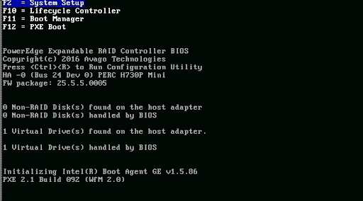
Power on your appliance
-
When prompted, press F2 to enter BIOS System Setup.
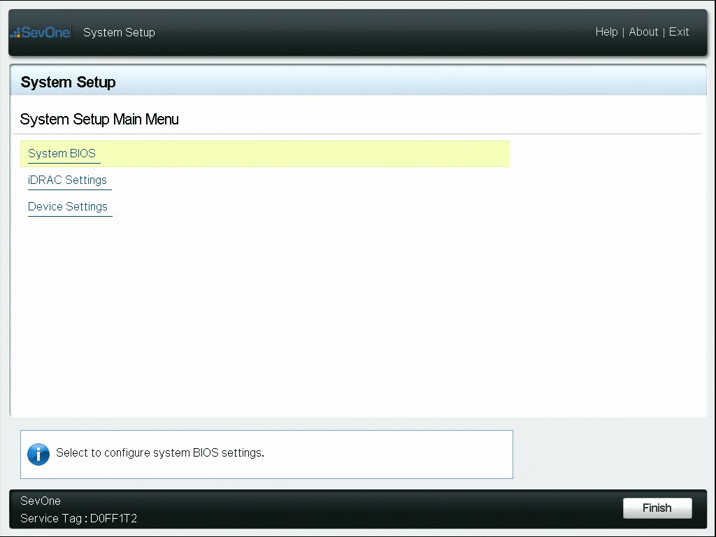
-
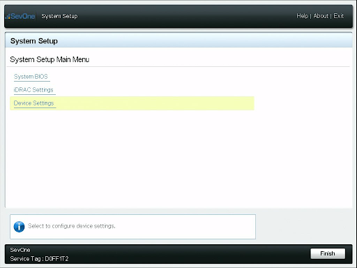
Select Device Settings.
-
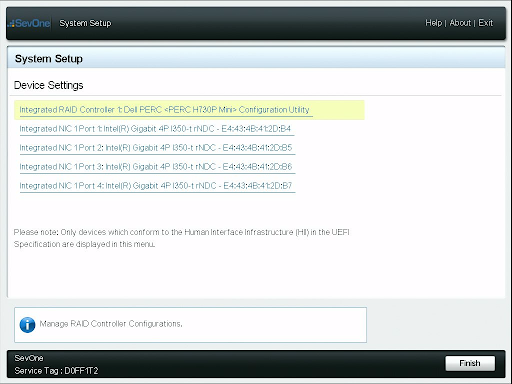
Select Integrated RAID Controller.
-
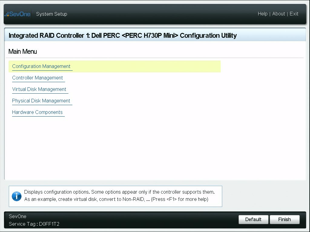
Select Configuration Management.
-
Select Clear Configuration.
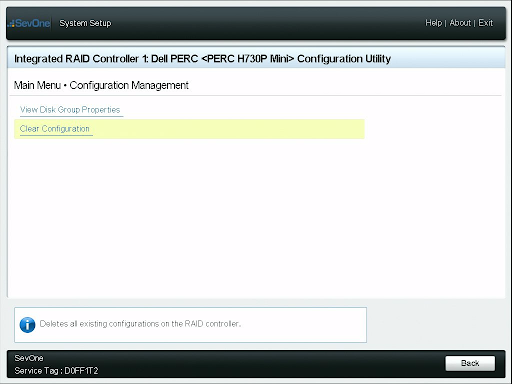
-
Select the Confirm check box and then click on Yes.
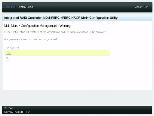
-
Select OK.
-
Click on the ESC key to return to the Main Menu.
-
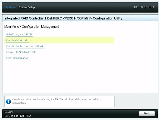
Select Configuration Management.
-
Select Create Virtual Disk.
-
Ensure Select RAID Level is set to RAID6.
-
Select Select Physical Disks.
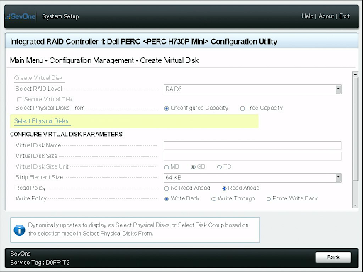
-
Ensure Select Media Type is set to Both.
-
Scroll-down and select Check All.
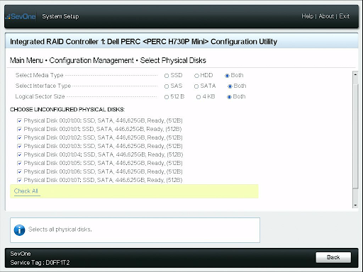
-
Scroll-down to the bottom of the page. Select Apply Changes and click on OK.
-
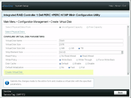
You are now on Create Virtual Disk page.
-
Ensure the following fields are set to:
-
Virtual Disk Name = Slash
-
Default Initialization = Fast
-
-
Select Create Virtual Disk.
-
Select Confirm check box and click on Yes.
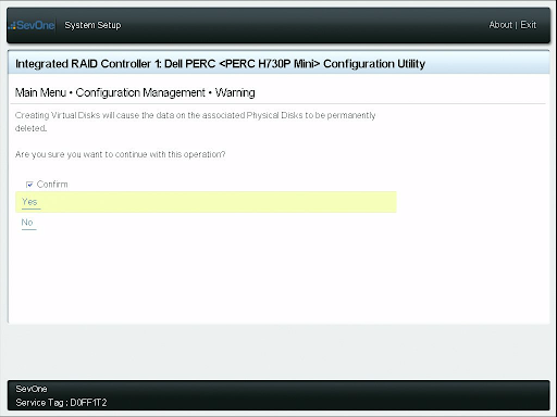
-
Click on OK.
If you receive the message Additional Virtual Disks cannot be created due to insufficient capacity or absence of configurable Physical Disks, you may ignore it.
-
Continue to click on the ESC key until you return to System Setup Main Menu.
-
Select Memory Settings.
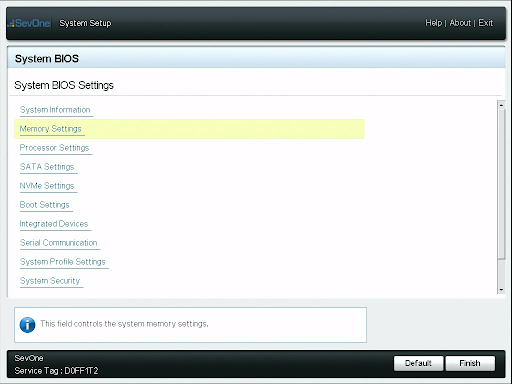
-
Ensure that Memory Operating Mode is set to Optimizer Mode.
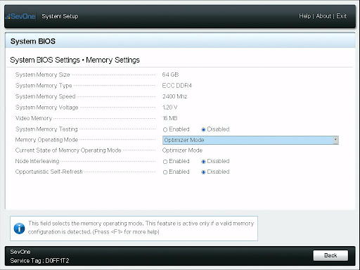
-
Click on the ESC key to return to System BIOS Settings page.
-
Ensure that Boot Mode is set to BIOS.
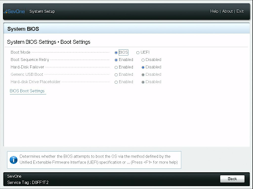
-
A reboot will be required if Boot Mode was previously set to UEFI. In this case, click on the ESC key until you receive a warning of Saving Changes.
-
Select the Yes option.
-
Confirm OK upon saving changes, and then click on the ESC key again.
-
You should be prompted to Confirm Exit and reboot the appliance.
-
Select Yes and then repeat Step 2, Step 23, and Step 27 to continue.
-
-
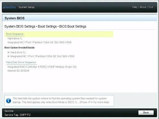
Select BIOS Boot Settings.
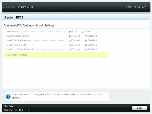
-
For Boot Sequence, confirm that Hard drive C: is the top option.
-
Click on the ESC key twice to return to System BIOS Settings menu.
-
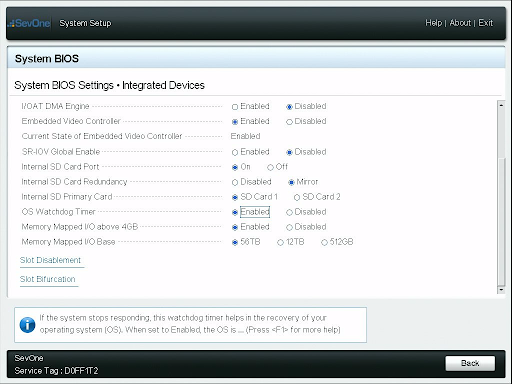
Select Integrated Devices.

-
Scroll-down to the bottom of the page and confirm that OS Watchdog Timer is set to Enabled.
-
Click on the ESC key to return to the System BIOS Settings menu.
-
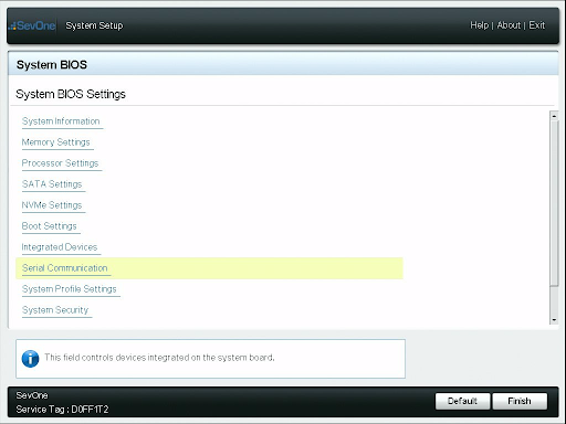
Select Serial Communication.
-
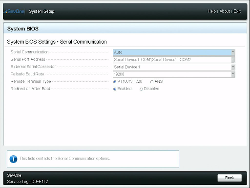
Ensure the following fields are set to:
-
Serial Port Address = Serial Device1=COM1,SerialDevice2=COM2
-
Failsafe Baud Rate = 19200
-
-
Click on the ESC key to return to System BIOS Settings menu.
-
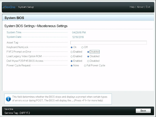
Scroll-down to the bottom of the page and select Miscellaneous Settings. Ensure the F1/F2 Prompt on Error is Disabled.
-
Click on the ESC key until you receive Saving Changes warning.
-
Select the Yes option.
-
Confirm OK upon saving changes, and then click on the ESC key again.
Your appliance is now pre-configured for RAID and BIOS!
Troubleshooting
How to fix a RAID Puncture
This section describes how to rebuild the RAID array if there is a puncture that has been identified by Dell. There are two types of initializations available in PERC (PowerEdge RAID Controller) - Fast and Full. For punctures, always swap the disks with one position and a Full initialization must be performed.
When following the steps below, you will encounter loss of all data on the array. Please use caution so that you do not impact any other arrays.
The process is borrowed from Dell's official website. For details, please refer to the link mentioned in the References section for topic PERC - How to Fix a RAID Puncture.
-
Discard Preserved Cache (if it exists).
-
Clear foreign configurations (if any).
-
Delete the array.
-
Shift the position of the drives by one. For example, if you have 3 disks, move Disk-0 to Slot-1, Disk-1 to Slot-2, Disk-2 to Slot-0.
-
Recreate the array as desired.
-
Perform a Full initialization of the array. Do not use Fast initialization.
-
Perform a Check Consistency on the array.
If the check consistency completes without any errors, you can safely assume that the array is now healthy and the puncture has been removed.
Generation 14
Please refer to section Hardware Configuration for details.
Generation 13
How to delete / recreate a RAID Virtual Disk
Occasionally, you may run into a situation where there may be a double fault in a RAID array and the array is no longer viable. This can happen when enough drives fail, that parity is lost or when there is a puncture. When this happens and the disks have been replaced, you will need to rebuild the RAID array and perform a partial rebuild.
If the RAID array is not failed, following the sections below can result in a total loss of data on the peer.
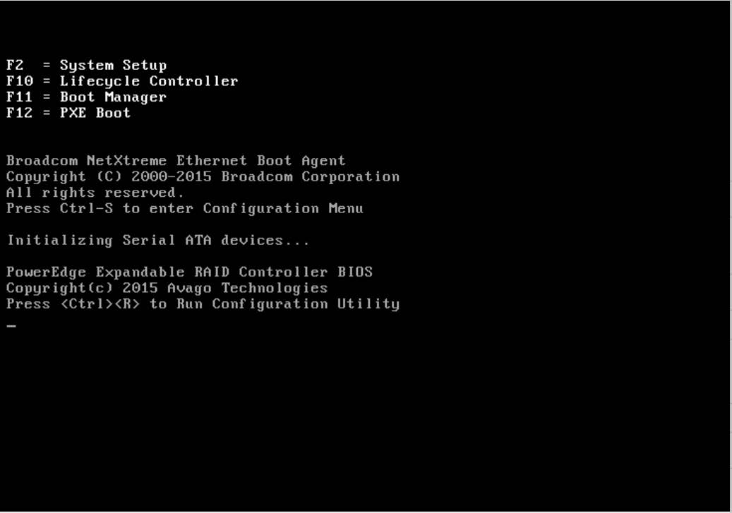
Boot to RAID Configuration Utility
While rebooting the appliance, press CTRL+R to enter PERC Configuration Utility when you see the options below.
Delete Failed RAID Array
By following the steps below, you will delete all contents of the partition and does not allow recovery.
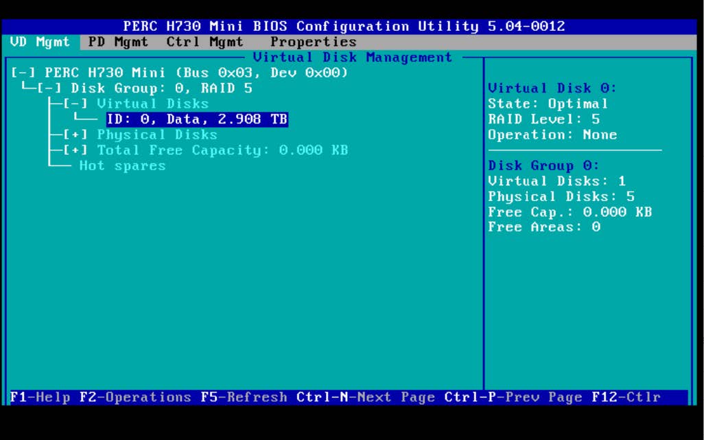
-
Use the arrow keys to select the virtual disk to delete.
-
Virtual disk 0 is the slash (/) partition.
-
Virtual disk 1 is the data (/data) partition.
-
-
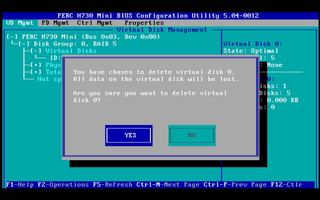
Navigate to the RAID Virtual disk you wish to delete. Press F2 for operation and scroll-down to Delete VD.
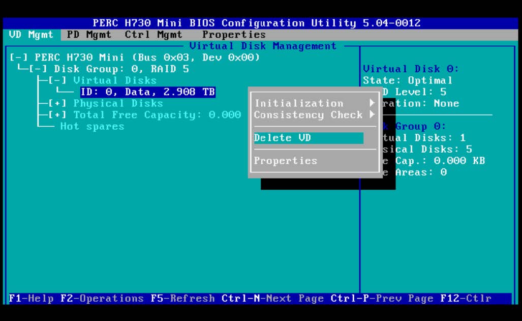
-
Click YES to confirm you want to delete the selected Virtual disk.
Create a new RAID Array
-
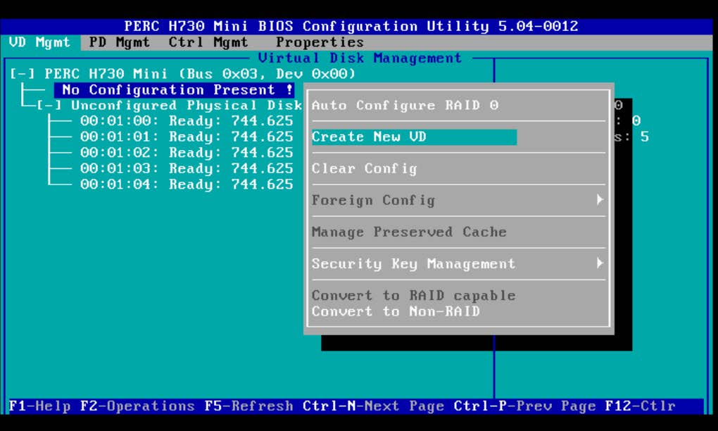
Navigate to the PERC Controller at the top and press F2. Use the arrow keys to navigate to Create New VD and press <Enter>.
-
Navigate this menu using TAB.
-
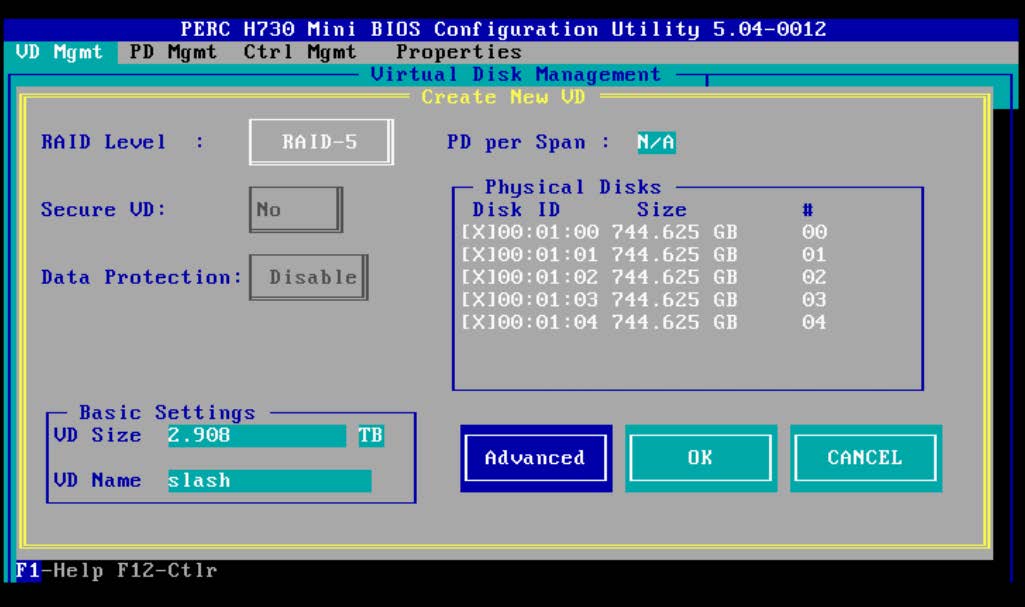
Select RAID Level: RAID-5 or RAID-6
-
Navigate to Physical Disks and hit <Enter> until all unclaimed physical disks are shown.
-
Under Basic Settings, VD Name must be slash or data depending on Virtual disk 0 or 1. If virtual disk 0, then this field must be set to slash.
-
TAB over to Advanced button and hit <Enter>.
-
-
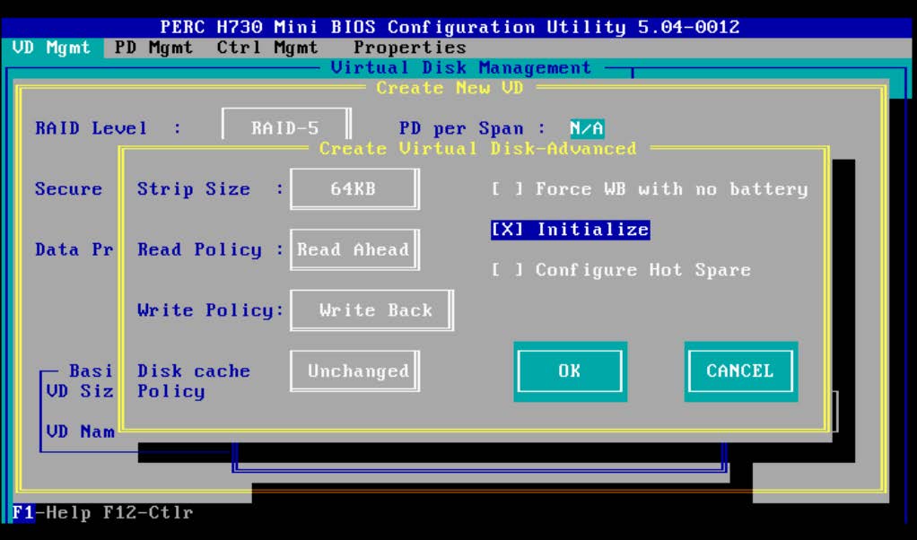
TAB through all settings until you reach [ ] Initialize. Select it by using <Enter> so that an X appears. TAB to OK and hit <Enter> to confirm that the initialization will delete the data on the drives.
-
TAB over to OK on the Virtual Disk Management page and hit <Enter> to initialize. This may take time depending on the size and number of disks in each array.
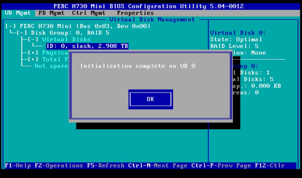
-
Press OK and click ESC (escape) key followed by Control+Alt+Delete to reboot.
RAID Arrays
SevOne's modern Generation 14 appliances utilize RAID 6 configurations. Prior generations utilize a combination of RAID 1 and RAID 5 configurations. For additional details, please refer to the link mentioned in the References section for Dell Servers - What are the RAID levels and their specifications? topic.
RAID Array Sizes by Model
Generation 14
|
Model |
Data Array |
|
PAS20k |
RAID 6: 5 Drives |
|
PAS60k |
RAID 6: 5 Drives |
|
PAS300k |
RAID 6: 8 Drives |
|
DNC200 |
RAID 6: 5 Drives |
|
DNC600 |
RAID 6: 5 Drives |
|
DNC1000 |
RAID 6: 8 Drives |
|
DNC1500HF |
RAID 6: 6 Drives |
Generation 13
|
Model |
Slash Array |
Data Array |
|
PAS20k |
RAID 1: 2 Drives |
RAID 5: 3 Drives |
|
PAS60k |
RAID 1: 2 Drives |
RAID 5: 3 Drives |
|
PAS200k |
RAID 5: 3 Drives |
RAID 5: 7 Drives |
|
DNC200 |
RAID 5: 2 Drives |
RAID 5: 3 Drives |
|
DNC600 |
RAID 5: 2 Drives |
RAID 5: 3 Drives |
|
DNC1000 |
RAID 5: 3 Drives |
RAID 5: 3 Drives |
|
DNC1000HF |
RAID 5: 6 Drives |
RAID 5: 6 Drives |
References
|
Automated Build / Rebuild (Customer) Instructions |
Please refer to Automated Build / Rebuild (Customer) Instructions for details. |
|
Dell Servers - What are the RAID levels and their specifications? |
|
|
Double Faults and Punctures in RAID Arrays |
|
|
How to initialize and create a virtual disk with a Dell PowerEdge RAID Controller (PERC) |
|
|
PERC - How to Fix a RAID Puncture |
https://www.dell.com/support/article/en-us/sln156726/perc-how-to-fix-a-raid-puncture?lang=en |